Using a visual Programming Utility to Create and Manipulate Sound
Month: January 2021
Deconstructing a natural sound involves analyzing the spectrum of the sound in order to recreate it using the various techniques of sound synthesis (additive, FM, subtractive, wave shaping, etc.). The sound you will create in this tutorial is the sound of a flute-like instrument called a RECORDER. Click below to hear a note played on a recorder:
After analyzing the spectrum of this sound and using that information to reconstruct it using additive synthesis techniques, you will create this sound:
You will use two applications in order to deconstruct and then synthesize the recorder sound: Amadeus II and SYD.
[Although SYD is available in versions for both Macintosh and IBM computers, Amadeus II is only available for Macintosh. There may be other spectrum analysis tools available for IBM computers but this writer is only familiar with MAC OS applications. GOOD LUCK!!]
If you need help with SYD, see the SYD Tutorials.
This tutorial will be divided into the following sections:
- Opening the Recorder AIFF sound file in Amadeus II
- Analyzing the spectrum of the Recorder sound file
- Converting the Decibel (dB) levels of the various frequencies to Amplitude values
- Creating the basic SYD patch
- Adding breath noise (to simulate the sound of the breath blowing through the Recorder mouthpiece)
- Adding the final sound characteristics
OPENING THE RECORDER AIFF SOUND FILE IN AMADEUS II
Begin by downloading the recorder sound file:
- Hold down the OPTION key on your Macintosh computer keyboard while you click on RecorderSound.aiff
- Save the sound file to your Local Workspace.
Launch the application, Amadeus II.
From Amadeus II, open the sound file you just saved, RecorderSound.aiff
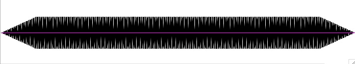
You should see the following:

Figure 1: Recorder Sound File as viewed from Amadeus II
ANALYZING THE SPECTRUM OF THE RECORDER SOUND FILE
Select a region of the sound file for which you will examine the frequency spectrum:

Figure 2: Recorder Sound File with region selected as viewed from Amadeus II
From the ‘Analyze’ pull-down menu in Amadeus II, select ‘Spectrum’:

Figure 3: Select ‘Spectrum’ in the Analyze pull-down menu in Amadeus II
Click ‘OK’ when you get the Spectrum Options window: 
You should see this graphic which is a representation of the individual frequencies (harmonics) of the note, A4 played on a recorder.

Figure 4: Sound spectrum of the note A4 played on a recorder as viewed from Amadeus II
Place the corsair (corsairs) exactly over the leftmost frequency in the spectrum:

Figure 5: Frequency and Decibel (dB) levels of the note A4 played on a recorder as viewed from Amadeus II
In a convenient location, write down the values of the frequency and decibel (dB) levels. Repeat this for each of the other two frequencies in the recorder spectrum. You should end up with these approximate values:
-
Table 1: Frequency and Decibel (dB) values
-
for the note A4 played on a recorder
-
as viewed from Amadeus II
The next step is to convert the decibel (dB) levels to real amplitude values on a 100% scale. You will be synthesizing the recorder sound using SYD. SYD uses amplitude values on a 100% scale and does not use decibel levels. The relative loudness of sound is usually referred to as the ‘sound intensity level’ and is based on the threshold of hearing at 1000 Hz. [For detailed information, check out SOUND INTENSITY LEVEL.]
Here is the formula:
y = the amplitude value we’re looking for
x = the decibel level from the above chart.
If x = 32.5, then
y = (10^3.25)/1000
y = 1.77827941
y = 1.78

After converting each decibel level, you should get the following amplitude values:
CREATING THE BASIC SYD PATCH
To synthesize the recorder sound using the frequency and amplitude values from the above table, launch SYD. See the SYD Tutorials if you need to review this application.
Create the following patch with a output duration of 4.0 seconds:

Figure 6: Basic Recorder Patch using SY
You could put an envelope on each of the three oscillators. But, because one of the amplitudes from the decibel (dB) to amplitude conversion table [Table 2. above] is > 1.0, it is best to patch the outputs from the oscillators through the mixer. This attenuates the amplitudes proportionally such that the overall amplitude coming out of the mixer is <= 1.0. Consequently, it is more convenient to put the envelope on the amplifier.
The recorder is a ‘woodwind‘ instrument (wind instrument) which requires wind pressure from the breath to produce the sound. The basic woodwind envelope [which would also include such instruments as flute, clarinet, oboe, bassoon, or any reed instrument which requires the human breath to produce the sound] looks like this:
Figure 7: Simple Woodwind Envelope

Here are the specific parameter settings for the woodwind envelope for the above patch:
Figure 8: Parameter settings for Woodwind Envelope using SYD

When you synthesize the patch, it should sound like this:
ADDING BREATH NOISE TO THE BASIC SYD PATCH
Adding breath noise to the basic recorder patch involves using the Butterworth filter set to BANDPASS mode. You will add three bands of noise roughly matching the three frequencies derived from the spectrum analysis above.
Here is the next stage of the Recorder Patch:

Figure 9: Basic Recorder Patch with Noise added using Butterworth Filters using SYD
Look for the three Butterwoth filters which have their output to a mixer and then to an amplifier, just like the Basic Recorder patch described above. In addition, the same envelope controls the amplifier for these additions.
In order to more easily control the noise level, an FTAB function has been incorporated. Here are the parameter settings for the FTAB:

Figure 10: Parameter settings for the FTAB function using SYD
The ‘Function’ field will contain the basic BANDWIDTH for each filter. Here is the format for using the FTAB function in the BUTTERWORTH filter:

Figure11: Parameter settings for the Butterwoth Filter using SYD
Note the format of the the FTAB function. The values in the parentheses (0,1) refer to the FTAB number and the value in the FTAB ‘Function’ field respectively. See the SYD User Manual for more detailed information on the use of FTAB. Each BUTTERWORTH Filter will have similar settings where the value in the ‘Freq’ field corresponds to the value of the corresponding frequency from the spectrum analysis above. The value which is multiplied with the FTAB function, is the amplitude for the corresponding frequency. Here is a table which shows these values:
|
Oscillator Frequency
|
Oscillator Decibel (dB) level
|
Oscillator Amplitude Value on a 100% Scale
|
Butterworth Filter Frequency
|
Butterworth Filter Band using FTAB
|
|
904
|
32.5
|
1.78
|
904
|
ftab(0,1)*1.78
|
|
1798
|
28.2
|
.66
|
1798
|
ftab(0,1)*.66
|
|
2702
|
23.2
|
.21
|
2702
|
ftab(0,1)*.21
|
-
Table 3: Frequency, Decibel (dB) and Amplitude levels for the Oscillators and Filters
-
for the note A4 played on a recorder.
When you synthesize the patch, it should sound like this:
Compare with the Basic Recorder Patch:
To increase or decrease the amount of noise you would like in your Recorder sound, change the value in the ‘Function’ field of the FTAB operator. A higher value (eg., 300) will give you a lot more noise; a lower value (eg., 100) will give you less noise.
ADDING THE FINAL SOUND CHARACTERISTICS TO THE BASIC SYD PATCH
[Sorry, not done yet.]
Try analyzing and then synthesizing the following musical instruments:
[To download the sounds, hold the OPTION key down and then click on the link.]
A Helicopter sound can be created by using noise patched through a filter. The RECIPROCATING sound of the helicopter blades can be simulated by one of two methods:
1. Use an LFO to open and close the bandwidth of the filter at a constant rate, OR
2. Patch the output of the filter to an amplifier and then use an LFO to turn the amplifier on and off at a constant rate.
The method presented here will be #1 (use an LFO to open and close the bandwidth of the filter at a constant rate).
Close any open SYD files.
Choose NEW under the FILE menu to open an empty Syd document.
Click and drag a RANDOM NOISE OPERATOR from the operator palate (that’s the one with the question mark on it — ?) down to the main part of the window.
Next, click and drag a BUTTERWORTH FILTER OPERATOR from the operator palate.
Connect the output of the RANDOM NOISE OPERATOR to the input of the BUTTERWORTH FILTER OPERATOR.
Connect the output of the BUTTERWORTH FILTER OPERATOR to the MAIN OUTPUT.
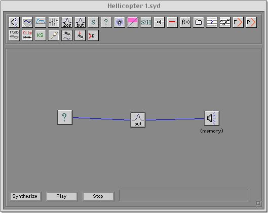
Your window should look something like this:
The RANDOM NOISE GENERATOR creates NOISE such that all frequencies and all amplitudes are randomly giving a steady output of what would sound like ‘radio static.’
The BUTTERWORTH FILTER is a variable band filter which allows four types of filtering:
– High Pass
– Low Pass
– Band Pass
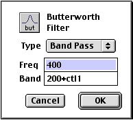
– Band RejectDouble-click on the BUTTERWORTH FILTER to open its edit window. It should look like this:
Set the values in the various fields so they show these values. Specifically, random noise will be passed to the filter. However, only a specific frequency of noise will be allowed to pass through (400 Hz). The BAND ‘width’ will be controlled by the variable, Ctl1. Think of the BAND WIDTH as the filter’s amplitude — the wider the band, the more noise passes through centered around the specific frequency contained in the FREQ field. In other words, the wider the band, the louder the noise. The value in the FREQ field controls the apparent pitch of the noise. A high value would allow ‘high-pitched’ noise to pass through. A low value would allow ‘low pitched’ noise to pass through.
Set the values in the BUTTERWORTH FILTER as pictured above and then click OK.
Specifically, you are setting the:
- TYPE = Band Pass
- Freq = 400
- Band = 200+ctl1 (the value ‘200+ctl1’ will be explained below)
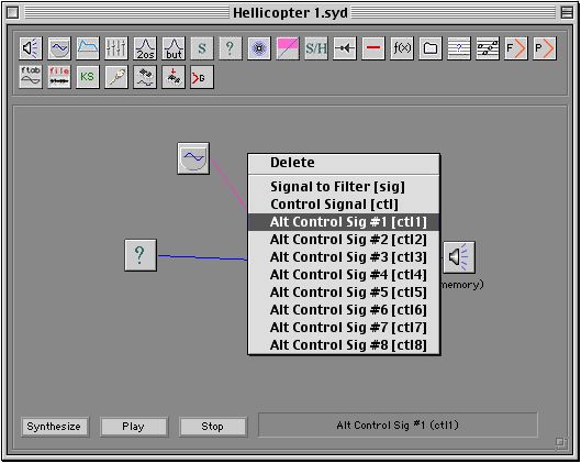
Now, drag an OSCILLATOR OPERATOR down into the window. Connect the output of the OSCILLATOR OPERATOR to the BUTTERWORTH FILTER.
Click and hold on the above connection and then select the connection type as: ALT CONTROL SIG#1 [Ctl1]. See below for detail:
Set the parameters of the OSCILLATOR OPERATOR to these values: Freq: 10; Amplitude: 200 (this oscillator will control the bandwidth of the filter by adding and subtracting 200 to the band width, thereby opening and closing the bandwidth).
Save your file.
Make sure the MAIN OUTPUT OPERATOR is set to MEMORY and not to FILE.
Synthesize your patch and then play it. It should sound like this (click below):
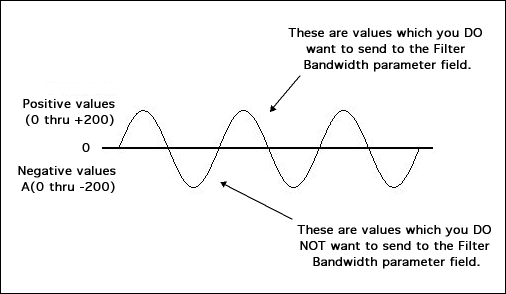
Explanation for including an offset in the Butterworth Filter Band field:
In the above patch, you are using a sine wave Oscillator to control the opening and closing of the bandwidth of the Butterworth Filter. This is what creates the characteristic oscillation of the ‘Helicopter’ sound. If you send just the control signal (ctl1) to the Band parameter field, then the Oscillator would send all values of the Sine Wave (positive and negative) to the Bandwidth parameter field.
To cancel out the negative values of the Sine Wave (0 thru -200), use an ‘offset’ in the Filter Bandwidth parameter field which is equivalent to the AMPLITUDE of the modulating Sine Wave:
If the overall output (volume) of the patch is not loud enough for you, then add an AMPLIFIER operator by patching the output of the filter through the amplifier. The finished patch might look like this:
Variations on the Basic Helicopter Patch:
Variation 1: Change the waveform of the LFO to a square wave (instead of a sine wave).
Variation 2: Change the frequency of the LFO to higher or lower values. A high value (60) might suggest some kind of buzzing machine such as a small airplane propeller or a motor boat.
[If you are having trouble understanding any part of the Helicopter Patch tutorial above, you may want to repeat earlier sections of the SYD TUTORIALS.]
Further Variations on the Basic Helicopter Patch
Instead of controlling the BANDWIDTH of the filter with an LFO, connect the output of the filter to an amplifier and then use an LFO to control the amount of amplification. Remove the LFO oscillator operator from the filter and set the filter values to (frequency = 400), (bandwidth= 200).
IMPORTANT: be sure to:
– use a SINE WAVE and not a SQUARE WAVE when controlling the amplifier.
– set the amplitude of the LFO to some value less than 6. (A value of 200 will set the amplitude of the Amplifier too high.)
Here is what the patch will look like:
Setting the frequency of the LFO on the above patch to values less than 8 will suggest sounds like:
– sand paper (1)
– the ocean (.1) [set the duration of the patch to 15 seconds]
LFO is an abbreviation for “low frequency oscillator.” Modulation refers to the way one signal is changed systematically by another signal. Consequently, LFO modulation refers to the process by which an oscillator using a low frequency (usually below the threshold of human hearing, 1 – 20 Hz) can systematically change the state of another oscillator, for example, its frequency.
Using the patch you created in the 1st tutorial (Creating a Simple SYD Patch), the following tutorial will show you how to use an LFO (low frequency oscillator) to modulate the frequency of the original sine wave operator. Systematic modulation of the frequency by a rate less than about 20 Hz (the optimum rate is 7 Hz) is also referred to as VIBRATO. Vibrato is the effect which is created when a string play “wiggles” the left hand on the finger board. It is also the effect that is characteristic of opera singers in the European tradition.
Do this:
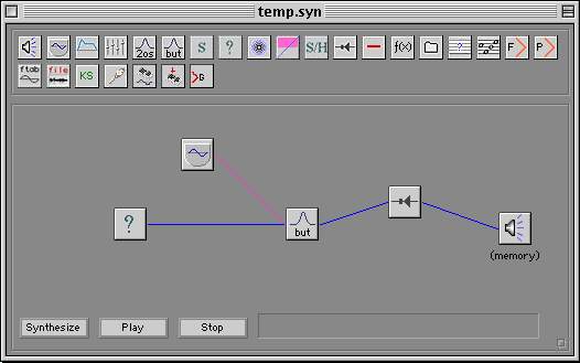
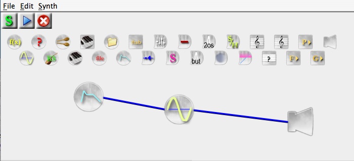
Open the LFO Modulation of the Amplitude patch you created in the last tutorial. It should look like this (except it won’t have the comment and arrows):
Move the cursor over the link you have made between the two oscillators until the cursor changes to a PEN (instead of a finger pointing).
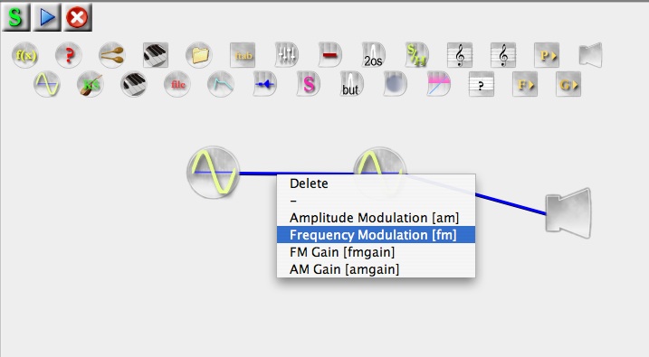
Hold down the CONTROL KEY and click on the connection until you get a pop-up menu.
Select the “Frequency Modulation (fm)” option:
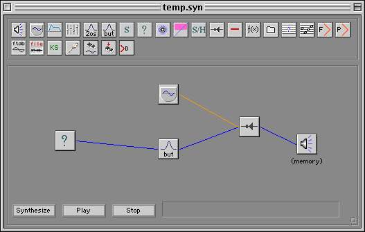
Note how the BLUE connection line changes to a GREEN connection line. This color coding is designed to alert you to the different types of connections, AM (amplitude modulation=blue) and FM (frequency modulation=green).
Select the original sine wave operator (the one on the right) and change the frequency field so that it contains the value, 440+fm (see below):
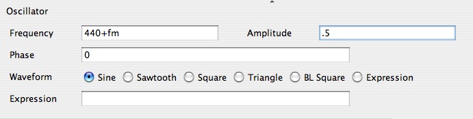
Also, change the value in the Amplitude field to .5 (be sure it’s 5 TENTHS and not 5).
Now select the LFO modulation oscillator operator (the one on the left) and change the various parameter fields so they contain these values:
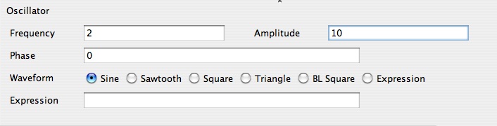
Note the value of 10 (!) in the amplitude field. Don’t worry, this is the correct value. This value of 10 is not the output amplitude but is the amount of modulation which will be added to the frequency in the original Oscillator operator. Later, you can experiment with changing this value to various amounts in order to discover how that will affect the sound.
Click OK and close this window.
Click the “Synthesize” button located in the bottom top corner of the patch window. You will not hear the sound of the patch until you “synthesize” it.
Make sure your headphones are connected to the audio output of the computer.
When you are ready to proceed, click the “Play” button located in the top left corner of the patch window. You should hear the sine wave play in your headphones and hear a definite modulation of the frequency corresponding to the 2 Hz frequency of the modulation oscillator. The depth (amount) of the modulation will be represented by the wide variation of the frequency. Or, click the link below to hear sound:
LFO is an abbreviation for “low frequency oscillator.” Modulation refers to the way one signal is changed systematically by another signal. Consequently, LFO modulation refers to the process by which an oscillator using a low frequency (usually below the threshold of human hearing, 1 – 20 Hz) can systematically change the state of another oscillator, for example, its amplitude.
Using the simple patch you created in the 1st tutorial (Creating a Simple SYD Patch), the following tutorial will show you how to add another operator which will modulate the amplitude of the original sine wave operator. Systematic modulation of the amplitude by a rate less than about 20 Hz (the optimum rate is 7 Hz) is also referred to as TREMOLO. Tremolo is the effect which is created on a vibraphone and with the voice which such singers as Kenny Rogers. Tremolo is also the effect which is produced when two tones sound togeter with a slight difference in frequency (see beats).
Do this:
Open the patch you created in the 1st tutorial.
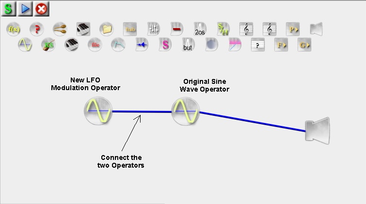
Add a second oscillator operator and connect it to the first operator so that it looks like this:
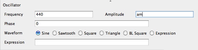
Select the ORIGINAL SINE WAVE OPERATOR (that’s the one on the right) and change the value in the Amplitude field so that it contains the variable, “am” :
Note the “am” in the Amplitude field. This is a VARIABLE through which the LFO will pass its values.
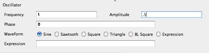
Now select the new LFO MODULATION OPERATOR (that’s the one on the left) and change the various parameter fields so they contain these values:
Click the “Synthesize” button located in the top left corner of the patch window. You will not hear the sound of the patch until you “synthesize” it.
Make sure your headphones are connected to the audio output of the computer. Also, it is assumed that you have already checked the system audio settings and your computer will produce audio output. Be cautious and place your headphones in front of your ears until you become familiar with this level of the sound.
When you are ready to proceed, click the “Play” button located in the bottom left corner of the patch window. You should hear the sine wave play in your headphones and hear a definite modulation of the amplitude corresponding to the 2 Hz frequency of the modulation oscillator. Or, click the link below to hear sound.
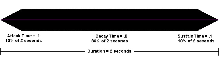
An ENVELOPE is usually defined as the shape of a sound’s amplitude over time (although an envelope can also be applied to other aspects of a synthesized sound such as the frequency, filter bandwidth, etc.).
Here is a graph of a simple ENVELOPE applied to the amplitude of the original Simple JSYD Patch (which was created in the 1st tutorial):
Click the link below to hear the sound:
An ENVELOPE with THIS shape is usually called a “woodwind” envelope and has a total of 3 points (nodes): ATTACK, SUSTAIN, DECAY. An envelope with this shape is typical of sounds made by BLOWING into a musical WIND instrument such as a clarinet, flute, oboe, etc.
A sound’s (amplitude) ENVELOPE is just as important to the overall recognition of the sound as the waveform itself. In the above sound with the envelope applied, there was a relatively short “attack“, a longer “sustain” and then a relatively long “decay.” These three terms are usually used to describe the basic points (nodes) of an envelope. If some kind of “controller” instrument is used (for example a keyboard) to play the sound when a key is pressed, then another point or NODE can be described for what happens when the key is RELEASED. Sophisticated synthesizers and software will have more than just 4 nodes.
An ENVELOPE is usually applied to the entire duration of the wave. For example, if the wave is 2 seconds long, then the envelope will also be 2 seconds long. The specific points or nodes of the envelope (ADSR) are then placed in varous proportions along the length of the wave. In the above wave (which is 2 seconds long), the attack is .1 (10%), the sustain is .8 (80%), and the decay is .1 (10%). These proportional values add up to 1.0 (100%) which represents the entire duration of the wave (2 seconds), in other words, 100% of 2 seconds. If the wave and envelope were each 6 seconds, then the nodes would still have the same proportions.
The following tutorial will show you how to add the above envelope to the 1st Simple SYD Patch which you created the first tutorial.
Do this:
- Close any open SYD files.
- Open the Simple SYD Patch you created in the first tutorial.
-
- Drag the Envelope Generator icon down to the patch window and make a connection to the Oscillator icon. It will look like this:
- Select the Oscillator icon.
- Change the value in the Amplitude field to the variable, “am” :
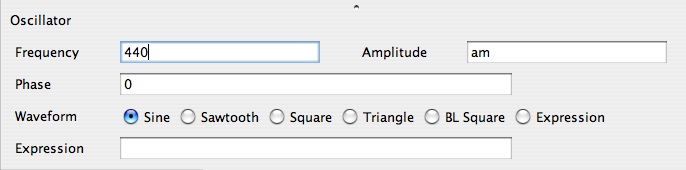 Note the variable “am” in the AMPLITUDE field. “am” = “amplitude modulation“
- Select the Envelope Generator operator.
- Carefully change the values in the various fields so they match the following values:
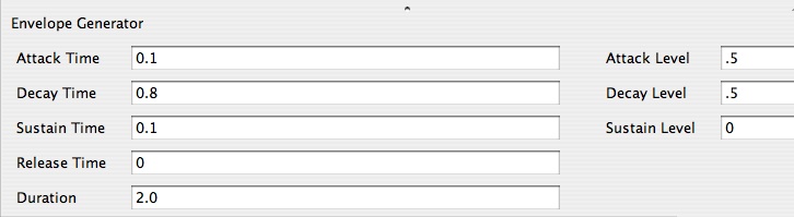
The values in the left fields represent the proportional TIME points or NODES of the envelope as described above (ADSR). The values in the right fields represent the actual amplitude LEVEL values which this operator will pass via the variable “am” in the amplitude field of the Oscillator operator.
Time vs. Duration
When you are ready to synthesize the sound, click the Synthesize button at the top left of the patch window. You will not be able to hear the sound until you synthesize it. Click your mouse somewhere in the window to deselect any operators and to view the Graph field so you will be able to see the ENVELOPE SHAPE you created.
Under normal conditions, the proportional values in the TIME parameter fields (Attack Time, Decay Time, Sustain Time, Release Time) should sum to 1.0 (100%). These individual values are proportional to the overall DURATION of the envelope. Also, under normal conditions, the DURATION of the envelope (in this case, 2 seconds) should match the DURATION of the overall sounds as set in the OUTPUT operator (2 seconds).
When you are ready to play the sound, click the Play button at the top left of the patch window. Or, you can click the like below to hear the sound:
The graphic shape of this envelope is that characteristic of Woodwind INSTRUMENTS, that is — musical instruments in which you blow your breath in order to produce a sound, such as a flute, oboe, clarinet, etc. Woodwind envelops have 3 points or nodes.
Try creating these other envelope shapes:
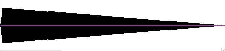
Percussion Envelope (2 points or nodes: Attack, Sustain) — sounds produced by hitting an instrument with a stick or mallet, such as a drum, bell, piano, etc
Percussion Envelope.aiff
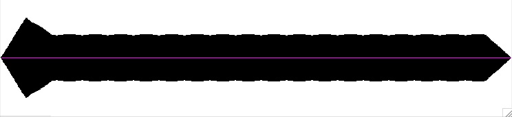
Brass Envelope (4 points or nodes: Attack, Sustain, Decay, Release) — sounds produced by instruments in which the lips are “buzzed” into a mouthpiece to produce a sound, such as a trumpet, trombone, horn, etc.
Brass Envelope.aiff
The FREQUENCY of the output of your patch is determined by a parameter in the Oscillator operator. Using the simple patch you created in the 1st tutorial (Creating a Simple JSYD Patch):
- Select the Oscillator operator.
- Change the value in the Frequency field to 220.
- You should see this window:

-
- Note the
-
- of .5. The
-
- form is a
- .
-
- MAKE SURE YOU HAVE ENTERED .5 (50%) in the AMPLITUDE field.
- Click the SYNTHESIZE button at the top left corner of the patch window. You will not hear the sound of the patch until you “synthesize” it.
- Make sure your headphones are connected to the audio output of the computer.
- When you are ready to proceed, click the PLAY button at the top left corner of the patch window. You should hear the sine wave play in your headphones. Or, click the link below to hear sound.sine2.aiff
Note that the FREQUENCY of 220 Hz is ONE OCTAVE lower than the FREQUENCY of 440 Hz.
FURTHER EXPERIMENTS: Try changing the values in the Oscillator parameters window: Remember, you have to RE-SYNTHESIZE the patch after change in order to hear the result
- Change the frequency to another value. For example, 110 Hz or 880 Hz.
- Change the amplitude to another value. For example, .25 (25%); .1 (10%); .75 (75%). Changing the value to 1.0 will produce the loudest sound with no digital noise (clipping) for the hardware of your computer. A value greater than 1.0 will produce a “clipped” wave that will no longer be a true sine wave and will sound more like a SQUARE WAVE.
IT IS NOT RECOMMENDED THAT YOU SET THE AMPLITUDE OF THE OUTPUT TO A VALUE GREATER THAN 1.0. IF YOU DO, MAKE SURE THAT YOU REMOVE YOUR HEADPHONES.
ALSO, IF YOU CHOOSE A WAVEFORM WITH A HIGH INTENSITY (SQUARE, SAW, ETC.) THE PERCEIVED LOUDNESS WILL BE MUCH GREATER THAN A SINE WAVE. KEEP THE AMPLITUDE LESS THAN .5 (50%). IF YOU INCREASE THE AMPLITUDE > 50% THEN MAKE SURE THAT YOU REMOVE YOUR HEADPHONES.
The amplitude of the output of your patch is determined by a parameter in the Oscillator operator. Using the simple patch you created in the 1st tutorial (Creating a Simple JSYD Patch):
- Select the Oscillator operator.
-
- You should see this window:

The default value in the Amplitude field is “1” — change this to .5
-
-
- Note the
-
-
-
- of 440 Hz. The wave form is a
-
SINE wave
-
-
- .
-
- MAKE SURE YOU HAVE ENTERED .5 (that’s “point – 5”) in the AMPLITUDE field.
- Click the SYNTHESIZE button at the top left corner of the patch window. You will not hear the sound of the patch until you “synthesize” it.
- Make sure your headphones are connected to the audio output of the computer. Also, it is assumed that you have already checked the system audio settings and your computer will produce audio output. PLEASE make sure you have entered a fractional (percentage) value into the amplitude field of the Oscillator parameter field. If you enter a number greater than 1 (100% – Unity), you may produce a sound that is so loud that it may damage your hearing if your headphones are placed directly over you ears. Be cautious and place your headphones in front of your ears until you become familiar with this setting.
- When you are ready to proceed, click the PLAY button at the top left corner of the patch window. You should hear the SINE wave play in your headphones. Or, click the link below to hear sound.Sine.aiff
FURTHER EXPERIMENTS: Try changing other values in the Oscillator parameters window, particularly the waveform. However, if you select SQUARE wave instead of SINE wave, the perceived LOUDNESS will be much greater. So, you should set the amplitude of a SQUARE wave at about HALF that of a sine wave. What would cause this effect?
To answer this question, draw a SQUARE wave along side a SINE wave on a sheet of graph paper. The SQUARE wave stays at the peak amplitude for a longer period of time than the SINEwave. Consequently, it has a greater average amplitude. It may seem like this proves the point — but it doesn’t. Draw a TRIANGLE wave beside a SINE wave and compare the overall average amplitudes. The TRIANGLE wave actually has an average amplitude LESS than a SINE wave but it has a greater perceived loudness. Consequently, something else must be going on.
Perceived loudness in tones with the same frequency is linked to the COMPLEXITY of the waveform — that is, how many HARMONICS. The more harmonics, the greater the perceived loudness. The SQUARE wave is a more COMPLEX sound than a SINE wave because it contains many harmonics. Compare the two sounds:
The SINE wave has no harmonics. For further understanding of this phenomenon see:
Remember, you have to RE-SYNTHESIZE the patch after every parameter change in order to hear the result.
IT IS NOT RECOMMENDED THAT YOU SET THE AMPLITUDE OF THE OUTPUT TO A VALUE GREATER THAN 1.0. IF YOU DO, MAKE SURE THAT YOU REMOVE YOUR HEADPHONES.
ALSO, IF YOU CHOOSE A WAVEFORM WITH A HIGH INTENSITY (SQUARE, SAW, ETC.) THE PERCEIVED LOUDNESS WILL BE MUCH GREATER THAN A SINE WAVE. KEEP THE AMPLITUDE LESS THAN .5 (50%) and even as low as .15 (15%). IF YOU INCREASE THE AMPLITUDE OF A SQUARE WAVE > 50% THEN MAKE SURE THAT YOU REMOVE YOUR HEADPHONES.
Under normal (programming) conditions, you will want to keep the OUTPUT set to MEMORY. However, if there is occasion for you to create a SOUNDFILE from your patch such as AIFF or WAV, then follow the procedure outlined below. [Outputting your patch as a soundfile DOES NOT automatically save the patch information itself as part of the soundfile. You cannot reconstruct the patch information, operators, parameters, etc., from a soundfile so you will still have to save the patch separately.
When directing the patch output data to a file (for example, AIFF or WAV), the file is INITIALLY created in the same directory as the JSYD.jar application which created it. This has important implications and you may end of writing the soundfile in some folder which you do not intend. You can select the directory to which you wish to write the soundfile:
1. Select the Output Operator to view its parameters
2. Make SURE the JSYD,jar window is expanded so you can see the “Select” button to the right of the Audio File parameter field:

The output of the patch (sound) is determined by parameters in the Output operator. There are three possibilities:
- Output to Memory
- Output to AIFF File
- Output to WAV File
The Radio Buttons select the type of output:
(1) Output to Memory — produces output directly to RAM.
(2) Output to AIFF File produces output to a soundfile in AIFF format (format Apple)
(3) Output to WAVE File produces output to a soundfile in WAV format (Windows).
If you select Output to AIFF File or Output to WAV File, the soundfile can then be further manipulated by a soundfile editor or simply played back as soundfiles from your WEB pages. Choosing output to AIFF or WAV files causes JSYD to write the digital information representing the sound directly to a file when you click the SYNTHESIZE button.
To output your SYD patch as an AIFF or WAV file:
1. Select the Output Operator and note the parameter fields.
2. Click on the radio button for AIFF or WAVE (see above graphic).
3. Click on the button “Select…” to the right of the Audio File parameter field. You will get a new window in which you can select the directory (folder) in which you wish to write the soundfile.
4 Locate the proper directory, name the file, and click the Save button.
IMPORTANT!! You are not through yet…
5. You still have to SYNTHESIZE (or re-synthesize) the patch or no data will be written to the soundfile. All you have done in the above steps 1-4 is to create a path to the directory in which you wish the soundfile to be written. THE SOUNDFILE IS NOT ACTUALLY WRITTEN UNTIL YOU CLICK THE SYNTHESIZE BUTTON on the top left of the JSYD window.

YOU MUST CLICK THE SYNTHESIZE BUTTON IN THE TOP LEFT CORNER OF THE PATCH WINDOW BEFORE THE SOUND FILE IS ACTUALLY CREATED (written) in the directory you selected.
The file ICONS are different for the SYD PATCH and for the AIFF and WAV files you export (write):
The basic JSYD file Patch is a TEXT file format with a “.syd” extension. The AIFF and WAVE files are in a standard SOUNDFILE format with either “.aiff” or “.wav” extensions.
It is GOOD PROGRAMMING PRACTICE to always name the output soundfile with the same FILENAME as the JSYD patch which created it. Note in the above example how Patch1.aiff was created by the JSYD patch, “Patch1.syd” and the Patch2.wav file was created by the JSYD patch, “Patch2.syd”.

NOTE: There are only minor differences in the file format of AIFF and WAV. Historically, AIFF is an Apple convention and WAV is a Window’s convention. Although, most soundfile editors will read and write both formats. Not all applications will work with both formats. Consequently, you may need to change the soundfile format using a soundfile editor.
The sample rate of the patch is determined by a parameter in the Output operator. The only reason you would need to change the sample rate would be if you are using a frequency which is greater than half of the sample. See Nyquist Limit. For example, if the sample rate is set to 22050 samples per second (Hz) and you were using a frequency greater than 11025 Hz, then you would need to set the sample rate higher, sat to 44100 Hz. Otherwise you would create a kind of digital noise known as ALIASING.
To set the SAMPLE RATE of your patch:
Open the patch you created in Tutorial2.
- Select the Output operator.
- You should see these parameters:

Note the value in the Rate field.
The value in the Rate field sets the SAMPLE RATE of the sound. Standard SAMPLE RATES include:
44100 Hz (standard CD sample rate)
22050
11025
It is not necessary to change the sample rate of your patch unless you are using a frequency that is greater than half the sample rate. See Nyquist Limit. Otherwise you create more data than is necessary to represent your sound. For example, at a sample rate of 22050 Hz, one minute of monophonic sound equates to approx 2.5 megabytes of memory or disk space. At 44100 Hz, one minute of monophonic sound equals 5 megabytes. A stereo sound would double the amount of memory or disk space.